Thursday, 18 October 2012

Step-by-Step guide to transfer FSMO roles in Windows Server 2008

The FSMO role holder is known as the Primary Domain Controller in a Domain. FSMO, also called Flexible Single Master Role will decide which DC should hold the Operation Master Role in a domain. During the installation of Domain Controller the FSMO role is automatically installed on the first server. If you have only one DC you don't want to do anything with the FSMO roles. But in a multiple server environment you may need to transfer the FSMO roles in some situations.There are totally five roles associated with FSMO.
  • This document will help you to transfer the FSMO roles to another DC.
The following are the five FSMO Roles :
  1. Schema Master Role
  2. Domain Naming Master
  3. RID Master
  4. PDC Master
  5. Infrastructure Master
You can use the command 'netdom query fsmo' to find out which DC is holding the FSMO roles.

This is an IMPORTANT thumb rule that you have to consider while transferring FSMO roles:

DO NOT place the Infrastructure Master Role in a DC where Global Catalog is configured unless all the Domain Controllers are configured as Global Catalog.

I will show how to manage Global Catalog in a DC latter in this guide.

Some Prerequisites

You have to follow this prerequisites before transferring FSMO roles.
  1. There should be a good connectivity between DC's.
  2. Proper Replication between DC's (You can use repadmin.exe to check the replication status and problems)
  3. Proper DC health (You can use dcdiag.exe to check the health of the DC)
  4. The DC that you are going to transfer should be configured as a NTP Time server (Refer http://yadhutony.blogspot.in/2012/10/ntp-time-server-configuration-in.html for configuration details)
To transfer the FSMO roles you can either use GUI or ntdsutil.exe in CLI. In our scenario I am going to use GUI to transfer the roles. 

Best Practises
  1. Schema Master and Domain Naming Master in one machine, which also hold the Global catalog
  2. PDC,RID (Infrastructure) in one machine.
  3. Do not place Infrastructure master role in a DC where Global catalog is enabled unless all the DC's are enabled with Global catalog
Also visit http://support.microsoft.com/kb/223346 for more details.

Transfering FSMO Roles

Scenario

>In our test scenario we have three DC's
The FQDN of the DC's are :
1. dc001.tony.com 2. dc002.tony.com 3. dc003.tony.com.
 
>Currently dc003.tony.com is the Operation master which hold all the FSMO roles in the domain tony.com.

>I am going to transfer the FSMO roles from dc003.tony.com to dc002.tony.com.
A.) Schema Master Role
 
We need to use Schema master snap-in to transfer the schema master role. To install the schema master snap-in you need to follow the below steps:
Register Schmmgmt.dll  
1.Open command prompt and type regsvr32 schmmgmt.dll

2.Click Start, click Run, type mmc, and then click OK
3.On the File, menu click Add/Remove Snap-in
 
4.Click Add

5.Click Active Directory Schema, click Add, click Close, and then click OK

Transferring Schema Master Role
1. Go to Schema master snap-in
 
2. Right-click Active Directory Schema and click Change Domain Controllers.
 
3. Now select the “domain controller” that you wanted to transfer the schema master role and click OK. In my case I need to transfer it to dc002.tony.com


4. Right-click Active Directory Schema and click Operation master > Change Schema master > Change 


Now the Schema Master Role is transferred to the preferred DC tony002.tony.com as you can see from the below screenshot.


B.) Transfer Domain Naming Master Role

1. Go to Active Directory Domain and Trust
2. Right-click the Active Directory Domain and Trust and click Change Active Directory Domain Controller

 
3. Now select the “domain controller” that you wanted to transfer the naming master role and click OK.


4. Right-click the Active Directory Domain and Trust and click Operation Master> Domain Naming Operation Master > Change.
Now the Naming Master Role is transferred to the preferred DC dc002.tony.com
  
 
C.) Transfer RID , PDC and Infrastructure Master

We can transfer these three roles using a single snap-in, Active Directory Users and Computers
1. Go to Active Directory Users and Computers
 
2. Right-click Active Directory Users and Computers > All Tasks >Change Domain Controller
3. Now select the “domain controller” that you wanted to transfer the operation master (RID, PDC, Infrastructure) role and click OK.


4. Right-click the Active Directory Domain and Trust and click Operation Master
Click RID tab > Click Change
  

5. Click PDC tab> Click Change

 
6. Click Infrastructure Master tab > Click Change

 
As soon as I try to change the Infrastructure master role I got a warning like “The Infrastructure master role should not be transferred to a GC server” Since all my DC's hold Global catalog I can safely ignore this warning and proceed. In your case DO NOT move Infrastructure master role unless all the DC's hold GC, else remove Global catalog and transfer Infrastructure master role.

 
Click Yes

By following the above steps you can successfully transfer the FSMO roles from one DC to another.
Also you can make sure that all the FSMO roles got transferred by running netdom query fsmo. See the result below:


  Administering Global Catalog in a DC

Global Catalog server hold the complete information about all the objects of its own domain. To know more about global catalog you can visit: http://technet.microsoft.com/en-us/library/cc730749.aspx

Here I am going to explain you how to enable or remove a Global Catalog Server.

1. Click Active Directory Sites and Services

2. In the console tree, double-click Sites, and then double-clicksitename”

3. Double-click Servers, click your domain controller, right-click NTDS Settings, and then click Properties.

4. On the General tab, click to select the Global catalog check box to assign the role of global catalog to the server.

5. If the check box was already ticked untick it to remove the global catalog from the server.


6. Restart the Domain Controller.

Friday, 12 October 2012

NTP Time Server Configuration in Windows Server 2008R2 and 2012R2

Introduction

Time synchronization is one one of the most important aspect in a modern computer network. Network Time Protocol (UDP 123) is the protocol designed to synchronize the clocks of your computers over the network. This tutorial will guide you to configure an NTP Time server in your network. This server will act like an authoritative time server in your domain which will serve the client computers. The NTP Time server in your network will get time from an external time source like time.windows.com or time.nist.gov or from the system BIOS. In our scenario I am going to configure an NTP Server in a PDC Emulator that will obtain time from an external source.But Windows recommend us to configure an NTP server to obtain the time from a hardware source for improved security and accuracy. So optionally I will mention how to get the time from an internal source too.


Here I am listing out few importance of Time synchronization in a network:

1. Effective DC & DFS Replication.

2. Tracking security breaches, network usage, or problems affecting a large number of components can be nearly impossible if timestamps in logs are inaccurate. Time is often the critical factor that allows an event on one network node to be mapped to a corresponding event on another.

3. To reduce confusion in shared filesystems, it is important for the modification times to be consistent, regardless of what machine the filesystems are on.
This document will help you to configure a NTP Time server in Windows Server 2008.

Enabling & Configuring NTP Server

1. Change the server type to NTP.
Click Start, click Run, type regedit, and then click OK.
Locate and then click the following registry subkey: HKEY_LOCAL_MACHINE\SYSTEM\CurrentControlSet\Services\W32Time\Parameters\Type
In the pane on the right, right-click Type, and then click Modify. In Edit Value, type NTP in the Value data box, and then click OK.

2. Set AnnounceFlags to 5. 
Locate and then click the following registry subkey: HKEY_LOCAL_MACHINE\SYSTEM\CurrentControlSet\Services\W32Time\Config\AnnounceFlags
 In the pane on the right, right-click AnnounceFlags, and then click Modify. In Edit DWORD Value, type 5 in the Value data box, and then click OK.


3. Enable NTPServer.
Locate and then click the following registry subkey: HKEY_LOCAL_MACHINE\SYSTEM\CurrentControlSet\Services\W32Time\TimeProviders\NtpServer
 In the pane on the right, right-click Enabled, and then click Modify .In Edit DWORD Value, type 1 in the Value data box, and then click OK.


4. Specify the time sources.
Open a command prompt and type the command as below: w32tm /config /manualpeerlist:peers /syncfromflags:manual /reliable:yes /update
peers: time.windows.com or time.nist.gov

eg: w32tm /config /manualpeerlist:time.windows.com /syncfromflags:manual /reliable:yes /update

5. At the command prompt, type the following command to restart the Windows Time service, and then press Enter:
    
net stop w32time 
net start w32time 

Some Useful commands

Make sure that you run these commands from an elevated command prompt

1. To resynchronize time : w32tm /resync  or w32tm /resync /rediscover
2. To verify the configuartion : w32tm /query /configuration and w32tm /query /status
3. Display the current time zone settings : w32tm /tz
4. To reset the registry settings of NTP server: 
     net stop w32time
     w32tm /unregister
     w32tm /register
     net start w32time
5. To synchronize time on a linux client : ntpdate server_IP


Allow UPD Port 123 through Firewall

Make an exception in your firewall to allow UDP port number 123.

Apply the NTP client settings via Group Policy(Optional)

Now we have to tell the client computers to obtain the time from the NTP Server. The policy is applied via GPO. The procedure is as follows:

1. Locate the Group Policy Object : Computer configuration/ Policies/Administrative Templates/ System /Windows Time Services/ Time providers

2.  Enable the below settings:
    Configure Windows NTP Client (In our case, it is the IP of the PDC)
    Enable Windows NTP Client


    Obtaining time from a Local Source (Optional)

    This configuration forces the PDC master to announce itself as a reliable time source and uses the built-in complementary metal oxide semiconductor (CMOS) clock. To configure the PDC master by using an internal hardware clock, follow these steps:

    1. Click Start, click Run, type regedit, and then click OK.
    Locate and then click the following registry subkey: HKEY_LOCAL_MACHINE\SYSTEM\CurrentControlSet\Services\W32Time\Config\AnnounceFlags
    In the right-pane, right-click AnnounceFlags, and then click Modify.
    In Edit DWORD Value, type A in the Value data box, and then click OK.
     Close Registry Editor.
     At the command prompt, type the following command to restart the Windows Time service:
        net stop w32time && net start w32time

    By accomplishing the above tasks you can configure an NTP server in your domain.

    For more information about NTP you can visit : http://www.ntp.org/

    Wednesday, 10 October 2012

    Installation and Configuration of WDS on Server 2008 R2

    Introduction

    Windows Deployment Services is a technology used to deploy Windows operating systems through a network. It is one the most convenient way to install an operating system in a corporate environment. The RIS (Remote Installation Service) is the forerunner of Windows deployment service (WDS ). WDS can be used to deploy Windows XP, Windows Vista, Windows 7 and Windows server 2008 operating system. There are two installation methods in WDS
    1. Attended installation - Installation that is performed by user interaction during its progress.
    2. Unattended installation - Installation that is performed without user interaction during its progress or with no user present at all.
    In this tutorial we are going to see:
     
    1. Step-by-step configuration of Windows Deployment Service in Server 2008 R2

    2. Creating an Unattended XML file using AIK

    3.Creating a Customized Image of Windows 7

    Task 1 : Step-by-step configuration of Windows Deployment Service in Server 2008R2

    Open the server manager in Server2008 R2 and click Roles > Add Roles.

    1. Select the Windows Deployment Service check box and click next.
     

    2. You will get a WDS overview screen, read it out and click next.


    3. You will be prompted to select the role services. As of now select both deployment server and Transport server. I will explain the functionality of the transport server latter. Click next.


    4. You will get a confirmation screen, click Install.


    5. The WDS installation will finish within a few minutes.


    6. You will get a confirmation page after the successful installation. Click close.


    Now you can see the WDS management console in All programs > Administrative tools. Open up WDS management console.
    7. When you open the console you will be notified that the WDS Server is not yet configured. Now we have to configure the server by going to the Action tab>Configure server.


    8. You will get a welcome page, verify the prerequisites and click next.


    9. Choose a folder to store all the configuration details of WDS. It will be much better if you can choose a drive other than the system volume.


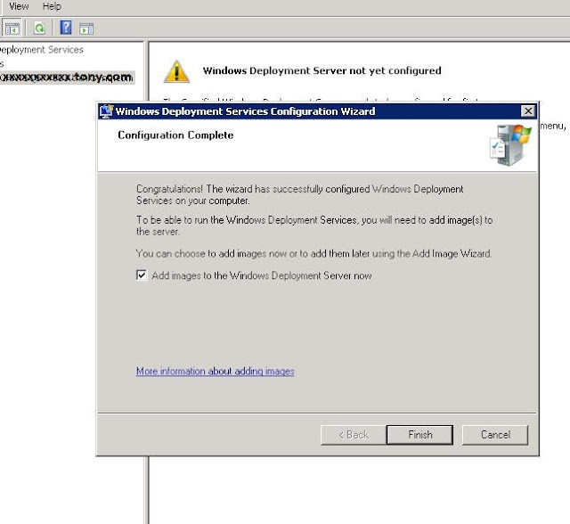
    10. WDS server configuration is completed. Click finish.


    11.Now you can upload install image and boot images for remote deployment.


    In our scenario I am going to add an image of windows 7. For this we need an installation disc of Windows 7. Insert the disc in your PC, explore it and search for the Source folder. Inside the Source folder you will see 'boot.wim' and 'install.wim' file. Copy these two files and paste it in a local drive of your WDS server.

    12. Right click the 'Boot Images' tab and click 'Add Boot Image' > Browse for the 'boot.wim' file which is stored in your local drive and click next.


    13.You can give the name and description of the image you are uploading.


    14. The boot image will be displayed as below after the upload.


    15. Add Install image by right clicking 'Install Images' and 'Add Install Image'. Browse for the 'install.wim' file and upload it to the server. After you upload an image you can see the image library as like below:

     
    16. The WDS server configuration is almost completed with the above step. Now we can fine tune the WDS services by right clicking the Server and going to the 'Properties' tab. Below you can see so many options in the server properties. But I am going to explain only about the unattended installation as it is one of the important feature of WDS


    Unattended Installation

    Unattended installation will help you to install the OS without any human intervention. The installation setup will run automatically by reffering the answer file that you have created.
    1. Switch on to the client tab and tick the check box “Enable unattended installation” and browse for the unattended xml file. The unattended answer file should be saved in your server's 'LocalDrive:\RemoteInstall\WdsClientUnattend' folder, which is created automatically once you install the WDS on your server 2008. I will explain how to create an unattended xml file later in this tutorial.

    2. Then go the image properties by right clicking the install image and tick the check box as shown below. Here you need to select a unattended.xml file which is stored on your local drive on your server.


    Task 2 : Creating an Unattended XML file

    To create an unattended xml file you can use the Windows AIK Tool kit or you can write your own xml file. Here I am using the Windows AIK Toolkit to accomplish the task.


    Download the Windows Automated Installation Kit from Microsoft website (http://www.microsoft.com/en-us/download/details.aspx?id=5753) and install it on your computer. You can download the software for free of cost from the Microsoft website.

    After the installation you can see the 'Windows System Image Manager' in All programs > Microsoft windows AIK > Windows System Image Manager.

    Open it and click 'Create an answer file' You will be prompted to select a Windows 7 image ('install.wim' file) and follow the instructions. Refer the screen shot below.


    After the image upload you will get a screen as below, where you can edit all the settings that you wanted to add to your answer file.


    In our scenario I am adding some settings like disk partition, automatically join the domain, IE home page etc in the answer file. Refer the following screen shots where you can find some of those settings.


    Once you finish adding all required settings in your answer file go to 'File > Save Answer file as' and save it with the name 'Autounattended.xml' and upload it to your WDS server. Below you can find the screenshot of an answer file that I have created. Also you can the check the following links for sample answer files: http://www.mockbox.net/windows-7-tips/149-windows-7-autounattend-example
    http://www.networknet.nl/apps/wp/archives/1402 

    Now you can boot the computer from the network and test the Windows Deployment Services. While you boot a computer from the network make sure that the PXE boot & LAN boot is enabled in the BIOS. If you enable unattended installation then the OS installation will start automatically with the PXE boot.

    Task 3. Creating a Customized Image of Windows 7

    While you install an operating system using WDS it is better to deploy a customized image of your OS. That will reduce the pain of installing the necessary softwares in each system after deployment.Here I am going to explain the steps to create a customized image of windows 7 using sysprep and imageX tool.

    For creating the customized image we need to have the below tools with us:


    >Windows AIK
    >Technician computer
    >Reference Computer (Which is installed with all the necessary softwares)

    1. Set up a Windows PE build environment

    • Install AIK on the technician computer
    • On the technician computer, click start, point to all programs,point to windows AIK, right-click Deployment Tools Command Prompt, and then select run as administrator.Then type the command as follows: copype.cmd x86 d:\winpe_x86
    • Copy the base image (Winpe.wim) to the \Winpe_x8r\ISO\sources folder and rename the file to Boot.wim. Type the command as follows:
      copy D:\winpe_x86\winpe.wim D:\winpe_x86\ISO\sources\boot.wim
    • Add imagex.exe to the winpe_x86\iso folder. Type the command as follows:
      copy "C:\Program Files\Windows AIK\Tools\x86\imagex.exe" D:\winpe_x
      86\iso\
    • Create an ISO Image of Install.wim File : oscdimg -n -bD:\winpe_x86\etfsboot.com D:\winpe_x86\ISO D:\winpe_x86\winpe_x86.iso
    • Burn the ISO image to a disc and label it as Windows PE boot image.

    2. Create the Image of the reference computer:

    • Now you have to go to the reference computer which is installed with all the necessary applications and run the sysprep. You can open up a command prompt and type the command as below:
      c:\windows\system32\sysprep\sysprep.exe /oobe /generalize /shutdown
    • After running the command the computer will shutdown automatically.
    • Now boot the reference computer from the Windows PE boot image disc that we have already created.
    • As as the computer boots you will get a command prompt. Move to the drive where the disc got mounted. Type the command as follows : imagex /capture C: C:\Install.wim“Win 7 x86 Proffessional” /VERIFY
    • Reboot the computer and check the C drive where you will find the Install.wim file.This is the image of your reference computer. Upload the Image to the WDS server and deploy.
    Troubleshooting

    I strongly recommend you  to check the logs by going to the Event Viewer before you begin troubleshooting.

    Monday, 8 October 2012

    Cisco IOS Zone-Based Firewall Step-by-step Configuration Guide

    Introduction

    The Cisco IOS Zone Based Firewall is one of the most advanced form of Stateful firewall used in Cisco IOS devices. The zone based firewall (ZBFW) is the successor of Classic IOS firewall or CBAC (Context-Based Access Control). Cisco first implemented the router-based stateful firewall in CBAC where it used ip inspect command to inspect the traffic in layer 4 and layer 7.

    Even though ASA devices are considered as the dedicated firewall devices, Cisco integrated the firewall functionality in the router which in fact will make the firewall a cost effective device. The zone based firewall came up with many more features that is not available in CBAC. The ZBFW mainly deals with the security zones, where we can assign router interfaces to various security zones and control the traffic between the zones. Also the traffic will be dynamically inspected as it passes through the zones. In addition to all the features which is available in classic IOS firewall, Zone based firewall will support Application inspection and control for HTTP, POP3, Sun RPC, IM Applications and P2P File sharing.

    For Advanced Configuration visit Zone Based Firewall Advanced Configuration

    Zone Based Firewall Vs CBAC

    CBACZone Based Firewall
    Interface Based ConfigurationZone Based Configuration
    Controls Inbound and Outbound access on an interfaceControls Bidirectional access between zones.
    Uses inspect statements and stateful ACLsUses Class-Based Policy language
    -Not supported-Support Application Inspection and Control
    Support from IOS Release 11.2Support from IOS Release 12.4 (6) T

    • This document is a Step-by-step guide to configure a basic zone based policy firewall in an IOS Router. This example is based on a 2900 series router running with 15.0(1) code.
    ZBFW Configuration Tasks

    The below are the configuration tasks that you need to follow.

    1. Configure Zones.

    2. Assign router interfaces to Zones.

    3. Create Zone pairs.

    4. Configure Interzone access policy (Class Maps and Policy Maps)

    5. Apply Policy Maps to Zone Pairs.

    Network Diagram

    The ZBFW configuration is based on the below network diagram.

    Figure 1:


    In this example we have three zones.
    • Inside Zone - Private LAN
    • DMZ Zone  - DMZ hosts
    • Outside Zone - Internet

    Here I am defining a rule set for our ZBFW:

    1. From Inside to Outside - http, tcp, udp, icmp and pop3 is allowed.

    2. From Outside to Inside - icmp is allowed.

    3. From Inside to DMZ - http, tcp and icmp is allowed

    4. From Outside to DMZ - http is allowed

    Default Rules of Zone Based Firewall

    1. Interzone communication is Denied, traffic will be denied among the interfaces that are in the different zones unless we specify a firewall policy.

    2. Intrazone communication is Allowed, traffic will flow implicitly among the interfaces that are in the same zone.

    3. All traffic to self zone is Allowed.

    Task 1 : Configure Zones

    In this example (refer figure 1) we have got three zones. Inside, Outside and DMZ.

    To configure zones in a router, connect the router via ssh or console, switch to the global configuration mode and type the command as below:

    Router(config)#zone security INSIDE

    Router(config)#zone security OUTSIDE

    Router(config)#zone security DMZ


    Task 2 : Assign Router Interface to Zones

    We have to assign the router interface to a particular zone. Here I am going to assign Gigabyte Ethernet 0/0 to INSIDE zone, Ge0/1 to OUTSIDE zone and Ge0/2 to DMZ zone.

    To achieve this we have to go to the particular interface and attach that interface to the zone. Type the command as below:

    Router(config)#interface gigabitEthernet 0/0
    Router(config-if)#zone-member securtiy INSIDE

    Router(config)#interface gigabitEthernet 0/1
    Router(config-if)#zone-member securtiy OUTSIDE

    Router(config)#interface gigabitEthernet 0/2
    Router(config-if)#zone-member securtiy DMZ
       

    Now if you try to ping a zone from another zone the traffic will be denied because of the default firewall policy.

    Task 3 : Create Zone Pairs

    Zone pairs are created to connect the zones. If you want to make two zones to communicate you have to create zone pairs. DO NOT create zone pairs for non-communicating zones. In our scenario the traffic flows between:
    • INSIDE to OUTSIDE
    • OUTSIDE to INSIDE
    • OUTSIDE to DMZ
    • INSIDE to DMZ
    So we need to create zone pair for all the four pairs. To create zone pair type the command as follows in global configuration mode.

    Router(config)#zone-pair security IN-TO-OUT source INSIDE destination OUTSIDE

    Router(config)#zone-pair security OUT-TO-IN source OUTSIDE destination INSIDE

    Router(config)#zone-pair security OUT-TO-DMZ source OUTSIDE destination DMZ

    Router(config)#zone-pair security IN-TO-DMZ source INSIDE destination DMZ


    Task 4 : Configure Interzone Access Policy

    Interzone Access policy is the key part of a zone based firewall where we classify the traffic and apply the firewall policies. Here we are defining the class-map and policy-map for classifying and defining policy to the traffic.

    Class Maps : This will classify the traffic

    Policy Maps : This will decide the 'fate' of the traffic.

    Class Map Configuration

    Class map sort the traffic based on the following criteria 1.) Access-group 2.) Protocol 3.) A subordinate class map. In this example we are sorting the traffic based on access group. So first we need to create an ACL and associate it with the class map.

    a.) Class Map for INSIDE-TO-OUTSIDE

    Router(config)#ip access-list extended INSIDE-TO-OUTSIDE
    Router(config-ext-nacl)#permit tcp 172.17.0.0 0.0.255.255 any eq www
    Router(config-ext-nacl)#permit tcp 172.17.0.0 0.0.255.255 any eq echo
    Router(config-ext-nacl)#permit tcp 172.17.0.0 0.0.255.255 any eq pop3

    Router(config)#class-map type inspect match-all INSIDE-TO-OUTSIDE-CLASS
    Router(config-cmap)#match access-group name INSIDE-TO-OUTSIDE

    b.) Class Map for OUTSIDE-TO-INSIDE

    Router(config)#ip access-list extended OUTSIDE-TO-INSIDE
    Router(config-ext-nacl)#permit tcp any 172.17.0.0 0.0.255.255 eq echo

    Router(config)#class-map type inspect match-all OUTSIDE-TO-INSIDE-CLASS
    Router(config-cmap)match access-group name OUTSIDE-TO-INSIDE

    c.) Class Map for OUTSIDE-TO-DMZ

    Router(config)#ip access-list extended OUTSIDE-TO-DMZ
    Router(config-ext-nacl)#permit tcp any 192.168.1.0 0.0.0.255 eq www

    Router(config)#class-map type inspect match-all OUTSIDE-TO-DMZ-CLASS
    Router(config)#match access-group name OUTSIDE-TO-DMZ

    d.) Class Map for INSIDE-TO-DMZ

    Router(config)#ip access-list extended INSIDE-TO-DMZ
    Router(config-ext-nacl)#permit tcp 172.17.0.0 0.0.255.255 192.168.1.0 0.0.0.255 eq www
    Router(config-ext-nacl)#permit tcp 172.17.0.0 0.0.255.255 192.168.1.0 0.0.0.255 eq echo

    Router(config)#class-map type inspect match-all INSIDE-TO-DMZ-CLASS
    Router(config-cmap)#match access-group name INSIDE-TO-DMZ

    
    Policy-Map Configuration

    Policy-Maps will apply the firewall policy to the class-map that is configured previously. Three actions can be taken aganist the traffic with the policy-map configuration:
    • Inspect : Dynamically inspect the traffic
    • Drop : Drop the traffic
    • Pass : Simply forward the traffic.
    There will be a drop policy, by default, at the end of the policy-map.

    a.) Policy-map for INSIDE-TO-OUTSIDE

    Router(config)#policy-map type inspect INSIDE-TO-OUTSIDE-POLICY
    Router(config-pmap)#class type inspect INSIDE-TO-OUTSIDE-CLASS
    Router(config-pmap)#inspect
    Router(config-pmap)#class class-default
    Router(config-pmap)#drop log

    b.) Policy-map for OUTSIDE-TO-INSIDE

    Router(config)#policy-map type inspect OUTSIDE-TO-INSIDE-POLICY
    Router(config-pmap)#class type inspect OUTSIDE-TO-INSIDE-CLASS
    Router(config-pmap)#inspect
    Router(config-pmap)#class class-default
    Router(config-pmap)#drop log

    c.) Policy-map for OUTSIDE-TO-DMZ

    Router(config)#policy-map type inspect OUTSIDE-TO-DMZ-POLICY
    Router(config-pmap)#class type inspect OUTSIDE-TO-DMZ-CLASS
    Router(config-pmap)#inspect
    Router(config-pmap)#class class-default
    Router(config-pmap)#drop

    d.) Policy-map for INSIDE-TO-DMZ

    Router(config)#policy-map type inspect INSIDE-TO-DMZ-POLICY
    Router(config-pmap)#class type inspect INSIDE-TO-DMZ-CLASS
    Router(config-pmap)#pass
    Router(config-pmap)#class class-default
    Router(config-pmap)#drop log


    Task 5 : Apply policy-maps to zone pairs

    Now we have to attach the policy maps to the zone pairs that we already created. The command is as follows:

    Router(config)#zone-pair security IN-TO-OUT source INSIDE destination OUTSIDE
    Router(config-sec-zone-pair)#service-policy type inspect INSIDE-TO-OUTSIDE-POLICY

    Router(config)#zone-pair security OUT-TO-IN source OUTSIDE destination INSIDE
    Router(config-sec-zone-pair)#service-policy type inspect OUTSIDE-TO-INSIDE-POLICY

    Router(config)#zone-pair security OUT-TO-DMZ source OUTSIDE destination DMZ
    Router(config-sec-zone-pair)#service-policy type inspect OUTSIDE-TO-DMZ-POLICY

    Router(config)#zone-pair security IN-TO-DMZ source INSIDE destination DMZ
    Router(config-sec-zone-pair)#service-policy type inspect INSIDE-TO-DMZ-POLICY


    There we finish the basic configuration of a zone based firewall.

    Troubleshooting

    Below you can find a list of commands for zone based firewall troubleshooting.

    a.) Show Commands

    show class-map type inspect

    show policy-map type inspect

    show zone-pair security

    b.) Debug Commands*

    *Use the debug command with great care.

    debug policy-firewall detail

    debug policy-firewall events

    debug policy-firewall protocol tcp

    debug policy-firewall protocol udp

    Useful Links